Suspension Geometry Calculator: A Practical Example
At the last race (Brands Hatch) I wasn’t too happy with the way the rear of the car felt. It was quite difficult to predict how it would behave entering Paddock Hill bend and required a lot of steering corrections through-out the corner. On returning to the garage and after stripping the car to begin some weight saving I alarmingly noticed a crack in the chassis where the rear lower trailing arm connects.

As you can see from the picture there is no lateral support allowing for chassis flex and as we all know if the suspension points aren’t solid then the suspension isn’t going to be up to much. With this in mind I knew I had to do something about it before the next race and so started to consider alternative mounting points.
Unfortunately, this isn’t the easiest chassis to work with when it comes to the live axle. The chassis was originally designed with IRS in mind and as such is quite wide at the rear. There is literally a 50mm (1 inch) gap the rear chassis and the edge of the tyre to squeeze the two trailing arms and remember when the suspension moves from maximum bump to droop the trailing arms will move laterally.
So, after much though I decided that lateral support as well as being mindful of the lack of space between the chassis and the tyre were of the upmost importance but that makes for some very short trailing arms. How will that affect the handling of the car? Will it introduce or increase the passive rear wheel steer? Cue the Suspension Geometry Calculator…
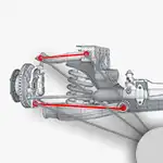
Let’s start with the old set-up
 This design really only came about because of circumstance. I’ve tried to show the maximum bump and droop in a lighter shade but you can of course click on the image to see the actual suspension in action. I have a maximum of 40mm (1.6″) bump and droop so 80mm (3.2″) of travel. In bump the axle changes position by 6mm, in droop it changes by 8mm so that’s 14mm (0.6″) of movement of it’s extents leading to a LOT of rear wheel steer. Check out my earlier videos before I had the stiffer anti roll bar… You can see that they usually involve a spin… No wonder.
Let’s see how the car will behave in future

First off check out how short those trailing arms are and can you believe that over 80mm (3.2″) of travel there is only 7mm (1/4″) of axle movement so much less rear wheel steer. I may even be able to back off my anti roll bar now. What’s also much better about this set-up is that the chassis mounting points are right at the back of the chassis where there is maximum lateral support so I’m hoping for some really predictable handling.
For me, this has been a great example of how the Suspension Geometry Calculator can take the guess work out of suspension design when it comes to designing or re-designing your suspension layout. Using my tablet in the garage I was able to quickly model a tweak the proposed layout so that rear wheel steer would be reduced and even tweak it so as the axle rotates, the differential is always in a good position relative to the output shaft.
If you want to model you own suspension layout then you need the Suspension Geometry Calculator.